contact
MOMus
Museum of Modern Art
Costakis Collection
21 st Kolokotroni Str.
Moni Lazariston
56430, Stavroupoli
Greece
Theremin Sensors Circuitry |
|
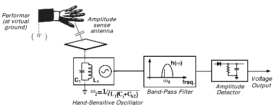
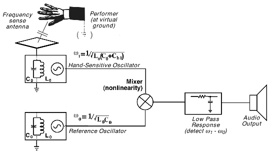
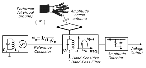
Analog T-Sensors, based on the classical theremin heterodyning principle, where realized in 1999-2003. Special circuitry was developed to produce super sensitive control. There are two basic versions of sensors: t-sensors to detect distance, providing the audio output with a pitch related to distance between the body and antenna; t-sensors to mesure velocity of changes (body movement near antenna, air flow, water drops near antenna etc.). The sensor and receiver were separated and connected to each other with a long cable (25 m.) to work with distant sensitive objects as a part of interactive installation, to analyse the motion of dancers or performers on stage etc. All controls were built in a receiver, normaly located near the operator's computer. Main advantage of this solution - there is no need in tuning of the system on stage. Any adjustment could be realized by an operator even during the performance which is very important for any interactive audio/video installations and live performance situations. Most recent digital USB D-Sensors, developed in 2005-2006, are based on alternative direct-control principle.
Unlike any classical theremin designs and previous T-Sensors, they have one main advantage - NO ANALOG TUNUNG IS NEEDED AT ALL! After any change of a hardware configuration system produce self adaptation and tuning by pure software means.
Any conductive media could be connected to the sensors as an antenna: metal objects, foil, water, human body, plants and vegetables, metal threads, thin plastic films with metallization, all sorts of Christmas stuff, conductive fabrics and clothes etc. to monitor variations of air flows, mechanical vibrations, changes of electrical capacitances of different conductive medias etc. There is no need in screwdriver to fight with coils! Just plug and play. D-Sensors are ideal for live interactive performance and long term interactive audio/video installations to avoid any need in continuous maintenance by the personal. |
|
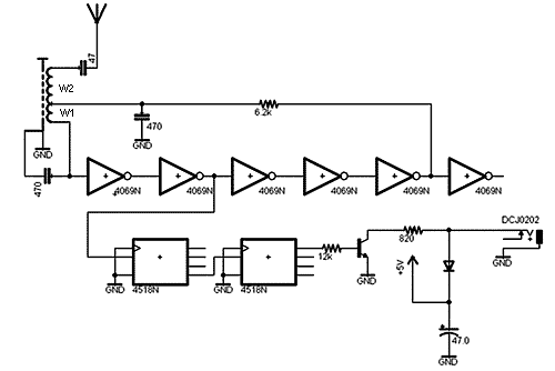
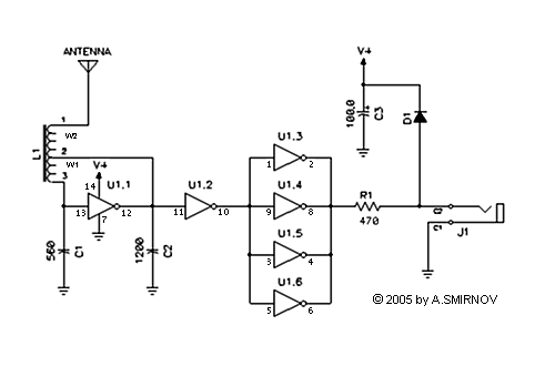
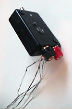
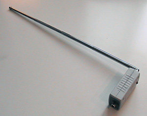
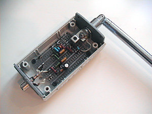
Theremin Sensor Kit The Sensor Kit contains the basic universal D-sensor circuitry oriented on both USB and Analog systems, convenient in case you need to analyse the motion of dancers and performers on stage or to work with distant sensitive objects as a part of interactive installation. Any conductive media can be connected to d-sensor as an antenna: metal objects, foil, water, human body, plants and vegetables, metal threads, thin plastic films with metallization, all sorts of Christmas stuff, conductive fabrics and clothes etc. to monitor variations of air flows, mechanical vibrations, changes of electrical capacitances of different kinds of conductive media etc. D-sensors are ideal for live interactive performance and long term interactive audio/video installations to avoid any need in continuous maintenance by the personal. Analog Theremin Sensor#1
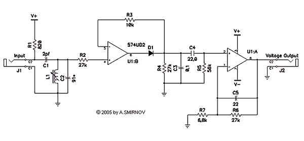
This sensor is convenient in case you need to analyse the motion of dancers and performers on stage or to work with distant sensitive objects as a part of interactive installation. The sensor is providing the output voltage proportional to velocity of changes of distance (body movement near antenna, air flow etc.). Sensor and receiver are separated. They are connected to each other with a long cable (25 m.). All controls are located at receiver side. Sensor: It is important to match frequencies of sensor oscilator and receiver oscilator. They should have similar initial values. Relation of the frequency of receiver oscilator and it's inductance L1 will be as following: 6.8 mH (milli Henri) will give you approximetely 130 khz, 1.8 mH - 230 khz, 0,5 mH - 370 khz, 0.44 mH - 500 khz, 0.27 mH - 800 khz, 0.082 mH - 1 mhz. |
|
Analog Theremin Sensor#2
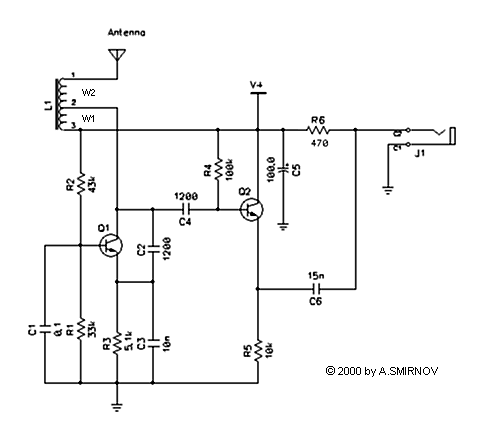
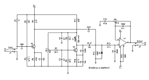
This sensor is convenient in case you need to analyse motion of dancers and performers on stage or to work with distant sensitive objects in the interactive installation etc. This sensor provids audio output with a pitch related to distance between a body and antenna. Sensor and receiver are separated. They are connected to each other with a long high frequency cable (25 m.). All controls are located at receiver side. Sensor: Q1, Q2 - high frequency transistor BC847, 2N2222, 2SC380 or any similar.
Receiver: It is important to match frequencies of sensor oscilator and receiver oscilator. They should have similar initial values. Relation of frequency of the receiver oscilator and it's inductance L1 will be as following: 6.8 mH (milli Henri) will result in approximetely 130 khz, 1.8 mH - 230 khz, 0,5 mH - 370 khz, 0.44 mH - 500 khz, 0.27 mH - 800 khz, 0.082 mH - 1 mhz. Q1, Q2 - high frequency transistors KT315 (Russian) BC847, 2N2222, 2SC380 or any similar. |
|
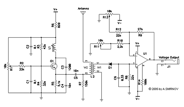
Analog Theremin Sensor#3
This sensor is a kind of analog controller to provide a control voltage to control analog synthesizer or computer in case you have extra voltage to MIDI or voltage to USB convertor (Arduino or JunXion box by STEIM could be perfect). It is not convenient for distant control since the antenna and all controls are united in the same box. Q1, Q2 - high frequency transistor KT315 (Russian) BC847, 2N2222, 2SC380 or any similar. L1 - any stable coil with apropriate inductance. It is important to match frequencies of the oscilator (L1, Q1) and resonant frequency of L2. They should have similar initial values. Connect C5 back to oscilator (Q1). After your sensor completely finished, installed in the propper case, antenna connected, put R1 in the middle position. Tuning the coil L1 and checking the signal on W1 (between s1 and s2) with osciloscope, find position when you have maximum signal on the maximum distance from the antenna and minimum signal when your hand is close to it. That's it. The relation of the frequency of oscilator and it's inductance L1 will be as following: 6.8 mH (milli Henri) will result in approximetely 130 khz, 1.8 mH - 230 khz, 0,5 mH - 370 khz, 0.44 mH - 500 khz, 0.27 mH - 800 khz, 0.082 mH - 1 mhz. U1 - Russian KP140UD1208 or any similar operational amplifier (uA776 etc.).
Power: any power supply +- 10 v (7810 & 7910 types). |
|
|
Learn More:
Extra Links:
|
|
